Lab 1
Wifi-Controlled LED Stoplight (Raspberry Pi)
Online Link
This lab is available as part of my online portfolio at: https://www.lehi.dev
Objective
The purpose of this lab is learn how to create a wifi-controlled stoplight. These principles include:
- Install and become familiar with raspberry pi OS.
- Enumerate requirements from use case and user stories.
- Develop a minimum viable product and refactor it to account for new requirements.
- Learn and use Github private repository and share it with a specific contributor.
- Become familiar with representing the desired system by using flowcharts, state diagrams, etc.
- Learn to plan what materials will be necessary to accomplish the system’s purpose
- Become familiar with coding in the Raspberry Pi
- Become familiar and learn how to use Raspberry pi GPIO
- Learn to run a server that accepts rest protocol to change raspberry pi GPIO stoplight state
Materials
- Personal Computer
- Raspberry pi 3 Model B Quad-Core 1.2 Ghz 1 GB RAM
- MicroSD card
- 2.5A USB Power Supply with micro USB Cable
- 1 x breadboard
- 1 x Red LED
- 1 x Yellow LED
- 1 x Green LED
- 3 x 220 Ω Resistor (RRBlBlBr)
- Jump wires
- GPIO pinout guide
References
The following resources were used in this lab:
- https://www.raspberrypi.org/documentation/installation/installing-images/ – This site provides guide to download RASPBIAN Operating System and writing the OS into a MicroSD card using Etcher application
- https://www.raspberrypi.org/magpi/thonny/ – Great site that teaches you how to use and debug Python using an IDE called Thonny
- https://blog.miguelgrinberg.com/post/designing-a-restful-api-with-python-and-flask – Great tutorial to get up and running on using flask for rest API
- https://www.tutorialspoint.com/flask/flask_templates.htm – This teaches how flask can also serve you html from the server and even ingest variables from API to the web page.
- https://www.bestcssbuttongenerator.com/ – CSS Button Generator resource.
- GPIO pinout guide (https://pinout.xyz/) – Great resource to find which pins to use.
- https://www.w3schools.com/howto/howto_css_switch.asp – Sliders reference.
- https://eli.thegreenplace.net/2017/interacting-with-a-long-running-child-process-in-python/ – Spawn a child process and terminate it.
- https://www.geeksforgeeks.org/global-local-variables-python/ – Python global variables.
- https://stackoverflow.com/questions/46349370/javascript-file-not-found-using-relative-path-during-flask-render-template – More about Flask project files structure.
- http://flask.pocoo.org/docs/0.12/patterns/packages/#larger-applications – Flask project structure.
- https://stackoverflow.com/questions/22259847/application-not-picking-up-css-file-flask-python – Flask html and css structure
Procedures
- Download and install Raspbian OS into raspberry pi from https://www.raspberrypi.org/downloads/raspbian/.
- Used the pre-installed Thonny Python IDE to develop the code for the stoplight.
- Used the GPIO pinout to decide which pins to use for this project from https://pinout.xyz/.
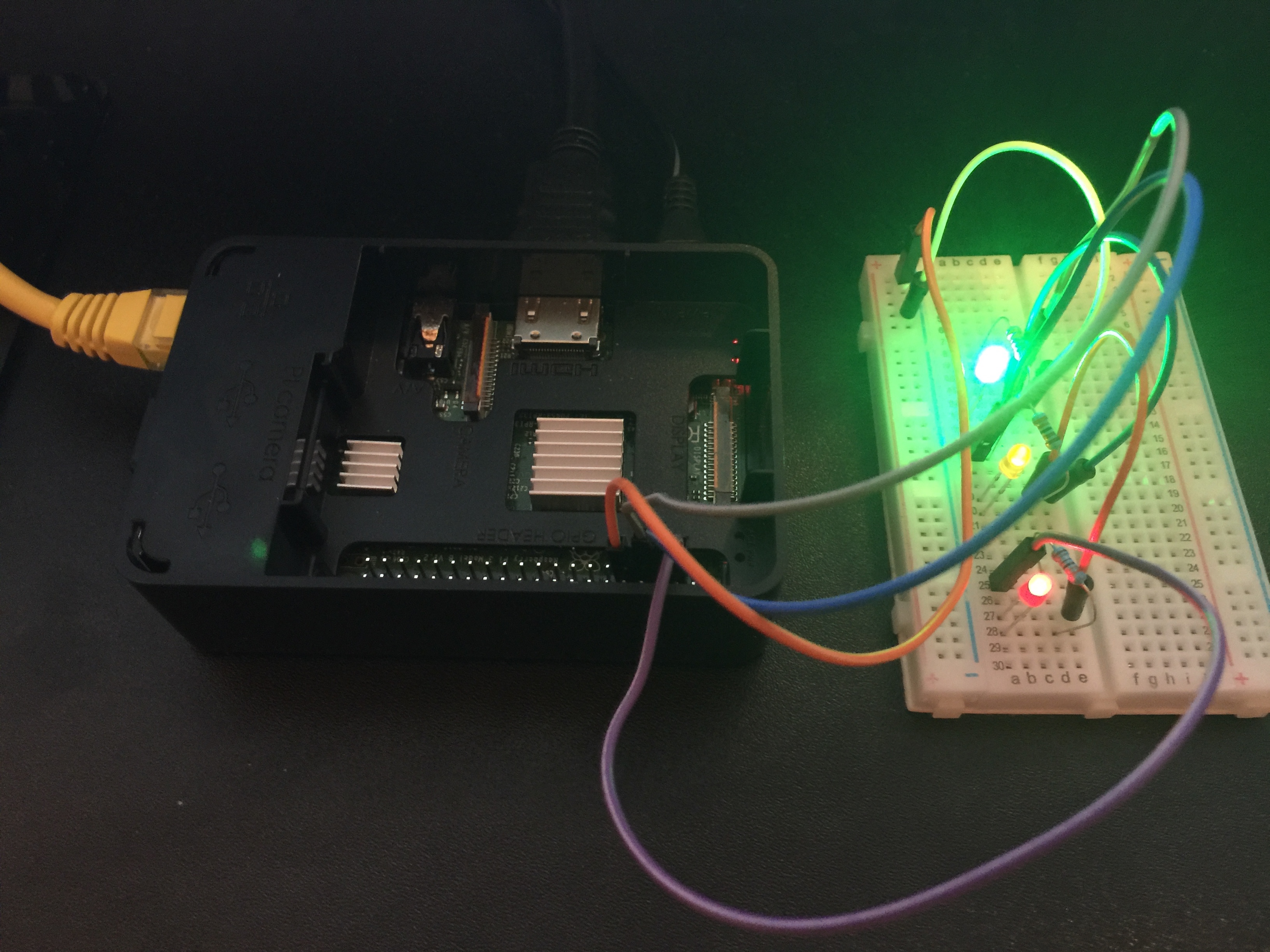
- In version 1 I wanted to design a system that all it would do was to turn on the lights according to the pins that were on.
- Chose the following pins to be on:
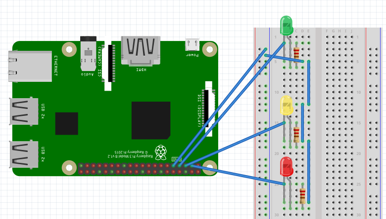
- Pin 7: Green color
- Pin 5: Yellow color
- Pin 3: Red color
- Pin 9: Ground
- Chose the following pins to be on:
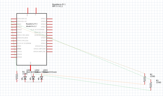
- Had a 220 Ω Resistor connected between positive and LED positive, although I could have also connected also in between Ground and negative side of LED negative and the effect would have been the same.
- I had one Ground pin from GPIO to breadboard negative column, then male jumpers connecting all 3 LED negatives.
- In version 2, once I got the lights to come on using GPIO commands then I included a python library server called Flask to facilitate Restful API calls to change state from the state machine as well as serving html page to send Ajax commands to the backend server. All endpoints served by Flask server returns a json payload with state machine information. I configured Flask to serve to any client that is in same network.
- For the case of blinking lights until another command would stop it: I opened a child process to run a python script file which contained an infinite loop through turning on and off the LEDs. I the kept track of that process. Created logic to check if there was already a process running to blink the lights if so don’t create a new one, if not then create a new process and keep track of it. When the slider is off I then sent the terminate signal to the process that the server is keeping track of.
- Models:
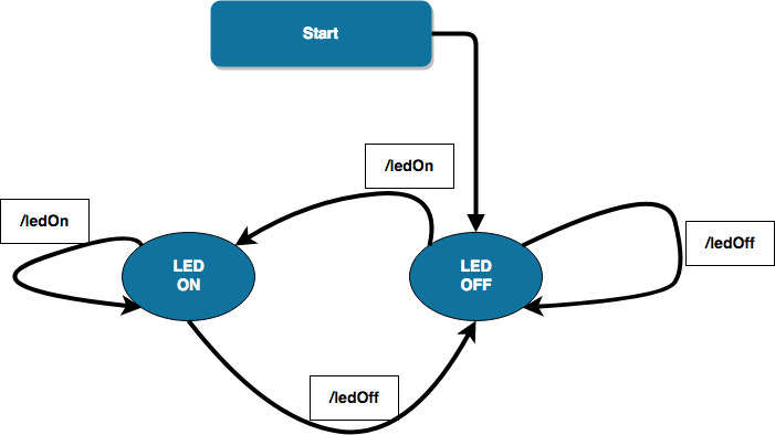
- Functionality: State machine as shown on the diagram below, this is a simplified form of the state machine as in reality I have created many endpoints to change the state machine for each led, but the basic concept is described below for each endpoint it reacts as the following diagram:
- On Start up, the machine will be on LED Off state
- Case “LED OFF”
- If system receives /ledOn then system changes to “LED ON” state.
- If system receives /ledOff then system remain in “LED OFF” state.
- Case “LED ON”
- If system receives /ledOn then system remains in “LED ON” state.
- If system receives /ledOff then system changes to “LED OFF” state.
-
-
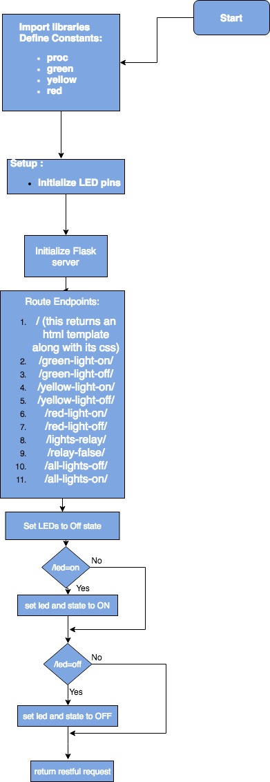
- System Flow: See Appendix 1.
- Component and Schematic Diagram: The stoplight system is represented below by the following diagrams (Component and Schematic Diagram respectively)
-
Diagrams were facilitated by open source programs such as: Google drive plugin draw.io Diagrams and Fritzing.
-
-
- Program the code in the Thonny Python IDE (pre-installed with Raspbian OS)
- Code the Raspberry pi GPIO interaction with breadboard, resistors, LEDs accordingly to match the previous component/schematic diagram.
- Test/Debug constantly so the final product would be bug free. You can debug in Thonny Python IDE by going to:
- Run > Debug Current Script (Ctrl+F5)
- Enable variables watch, this will help to see the value of variables at a given part of the code as you step over or step in the methods you have coded.
- View > Variables
- Program the code in the Thonny Python IDE (pre-installed with Raspbian OS)
-
Thought Questions
-
-
- What language did you choose for implementing this project? Phyton Why? Because it is a well versed language that can do many things and it is already includes libraries such as GPIO that can communicate with raspberry pi.
- What is the purpose of the resistor in this simple circuit? What would happen if you omitted it? “The main function of resistors in a circuit is to control the flow of current to other components. If too much current flows through an LED it is destroyed. So a resistor is used to limit the current.” (http://www.madlab.org/electrnx/lesson2.html)
- What are practical applications of this device? What enhancements or modifications would you make? This is mainly to get started with raspberry pi GPIO and facilitate the learning on how to interact from raspberry pi and a breadboard for instance. In regards to enhancements, I would create more endpoints to check on current state of the state machine and add UI logic to behave accordingly, so that once a slider is activated then it deactivates the other sliders, thus eliminating out of state synch issues. Another enhancement would be to make it so that the UI always have the current state of the stoplight no matter how many clients connects to stoplight server, that may be tricky because it may require more client calling back and forth the back end server, potentially making it inefficient by calling backend too many times.
- Please estimate the total time you spent on this lab and report.
- 1.5 hrs building and refactoring the circuit
- 6 hours coding the server and fixing bugs and getting acquainted with GPIO coding and setting up a Restful server using Flask Python library
- 4 hours working on the lab report using tools such as Google draw.io Diagrams and fritzing.
- 2 hours publishing a website with lab 1 instructions, mainly dealing with formats.
-
Certification of Work
I certify that the solution presented in this lab represents my own work. In the case where I have borrowed code or ideas from another person, I have provided a link to the author’s work in the references, and included a citation in the comments of my code.
— Lehi Alcantara
Appendix
Appendix 1: System Flowchart
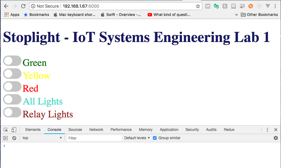
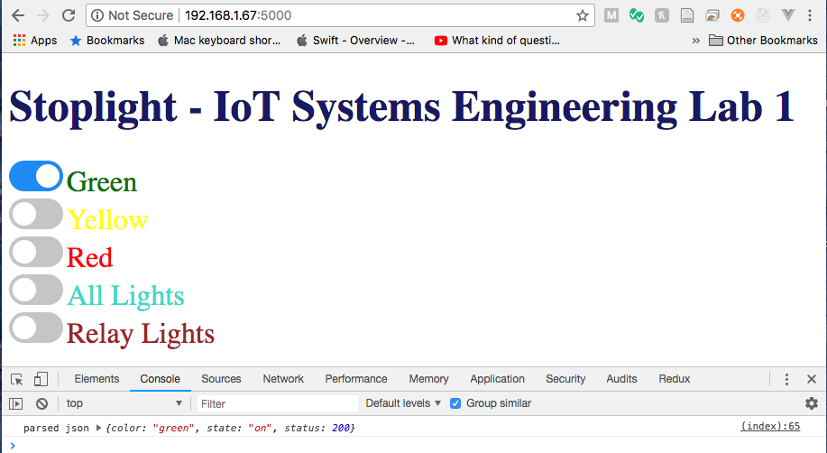
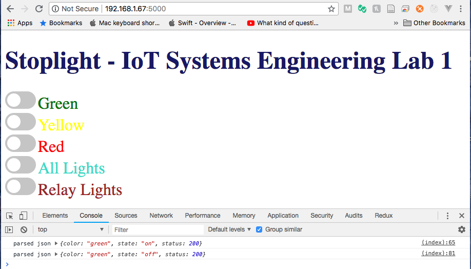
Appendix 2: System Interface – Web Page
State: startup
State: greenLightOn
State: greenLightOff
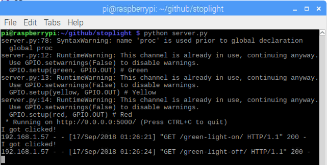
Appendix 3: Server Monitor Output
Appendix 4: Raspberry Pi Code
(Available at https://github.com/ylehilds/stoplight)
Comments
Post a Comment