Lab 6
IoT User Interface – Garage Door
Online Link
This lab is available as part of my online portfolio at: https://www.lehi.dev
Objective
The purpose of this lab is to learn how to use a relay to control your garage door Opener. Establish complex conditions by an additional sensor, these principles include:
- Implement Restful API to facilitate data transfer from sensors
- Develop a full feature UI interface displaying data states from sensors
- Implement a non user interface to open the garage door
- Enumerate requirements from use case and user stories.
- Become more familiar with representing the desired system by using flowcharts, state diagrams, etc.
- Learn to plan what materials will be necessary to accomplish the system’s purpose
Materials
- Personal Computer
- 2 x Wemos D1 Mini microcontrollers (ESP8266)
- 2 x 2.5A USB Power Supply with micro USB Cable
- 1 x raspberry pi with SD micro sd card and charger
- Arduino IDE
- Soldering iron
- Solder
References
The following resources were used in this lab:
- https://www.esp8266.com/viewtopic.php?t=2153 – Simple rest api example.
- https://mancusoa74.blogspot.com/2018/02/simple-http-rest-server-on-esp8266.html – Great tutorial on web erver Rest Api.
- https://www.howtogeek.com/221555/how-to-create-geographic-event-triggers-with-your-smartphone-and-ifttt/ – Great tutorial on how to get IFTTT geographic event trigger.
- https://blog.benjie.me/building-a-slack-bot-to-talk-with-a-raspberry-pi/ – Great resource on how to get a slack python bot running locally on a raspberry pi.
- https://www.geeksforgeeks.org/get-post-requests-using-python/ – Greate resource on how to use requests python library to make Rest calls.
- https://learningsuite.byu.edu/plugins/Upload/fileDownload.php?fileId=72cd766b-K3QH-e9vg-Jd1t-j889cf1046ea – Lab 6 requirements.
Procedures
- Having done all the previous lab to make a collection of ESP8266 along with sensors to send data amongst themselves (ultrasonic sensor, stoplight, reed switch, raspberry pi running mosquitto) and the relay sensor which is not connected with the other sensors since its whole purpose is to send a pulse to garage door opener to open the garage, now it is time to create Restful Api endpoints to each resource as to extract information from them as well as send commands like a pulse command to the relay to open the garage.
- In this lab I soldered 2 extra ESP8266 to act as a Restful Api server and the other to act as the website UI interface to display sensors state as well as send a command pulse to the relay sensor as to open the garage door.
- Instructions for the ESP8266 Restful API server:
- Use the ESP8266WebServer library as to serve endpoints that will be exposed for clients to hit it.
- Create different endpoints for each sensor in order to expose the data extraction from the sensor.
- Use ArduinoJson library to work with json responses from each sensor as to return the response to the clients.
- Use ESP8266WiFi to connect to wifi. PubSubClient library to connect to mosquitto message broker. Add your secrets and keys to a file and put it into .gitignore so that is not sent to github and expose passwords to the world.
- On each endpoint publish to a topic that the sensor is listening to and then subscribe for their responses in order to get their responses.
- Once data is collected back from sensors then send it back to the client requestor in json format.
- The json data can be utilized by both a website as well as a slack bot
- Instructions for the ESP8266 Website:
- Use ESP8266WiFi to connect to wifi. Add your secrets and keys to a file and put it into .gitignore so that is not sent to github and expose passwords to the world.
- Start server to serve the website that will display sensors state and a command to the relay to send a pulse to the garage door opener.
- Create a website variable and keep appending to it with the website contents including css and javascript that have functions that will send “fetch” web requests to the backend server to get data from the sensors.
- Once response is back from the backend server, update the sensors state on the website UI by finding a html element by Id then update its content.
- How to achieve the Non user interface as to make it easy for Don Borthwick so that when he gets close to his home the garage door opens it for him easier than him pushing a garage door button:
- Go to https://ifttt.com/discover website and look for an app called: “If you enter an area, then make a web request” add the service to your account, set the geographical trigger and send a post to a slack bot. In the body of the post request send the bot command you would like the bot to be triggered, in this case something like “open the garage door”
- Sign up for a slack account at https://slack.com:
- Create a channel
- Create an app
- Create a slack bot
- Keep track of the bot token
- Enable webhook incoming requests to post to a specific channel you have created earlier.
- Keep track of the webhook URL
- Allow a bot to post to a specific channel
- How to create a bot script:
- Import json, requests, slackclient use pip install on 3rd party libraries
- Use your bot token to use with slackclient library
- Get slack user id from bot name
- Connect to slack
- Create an infinite loop that looks for messages
- Filter out the message you want the bot to act on
- If garage door is opened do nothing, if garage door is closed then send a pulse request to the relay sensor in order to open the garage door opener.
- Post back to the slack channel to inform user whether the bot was successful in doing what you wanted it to do.
- Add retry logic on the http requests, just in case a request fails for some reason, also add timeout so that a request doesn’t wait for too long.
- How the overall system is secured:Implemented some network rules, for instance:
- No more sharing network credentials with neighbors
- Change all default passwords
- Using strong network encryption such as WPA AES
- Create a guest network that is separate from the main home network
- Only connect important devices to a separate network specialized to only have a few devices as long as it is not the open guest network.
- Review network logs and which devices are attached to your network as to make sure there is no hacker connected.
- Got a network switch that has Auto DoS prevention, this will protect your network from DOS attacks.
- On your wifi router disable Port Scan and enable DoS Protection, which will protect you wireless network from attacks.
- Slackbot Token is saved on a secured location and not pushed to github
- Slack Webhook url is also saved on a secured location and not pushed to github
- API specifications:
- Distance:
- Allowed http protocol: GET
- /distance is the endpoint
- Returns distance and whether the car is parked
- Door:
- Allowed http protocol: GET
- /door is the endpoint
- Returns door state: open or closed
- Relay:
- Allowed http protocol: GET
- /relay is the endpoint
- Sends a pulse to the garage door opener
- Distance:
- Models:
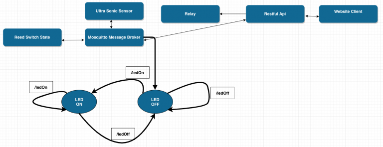
- Functionality for the Restful Api: Restful Api as shown on the diagram below.
-
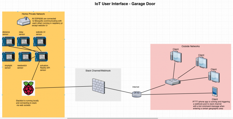
- Overall System Diagram.
-
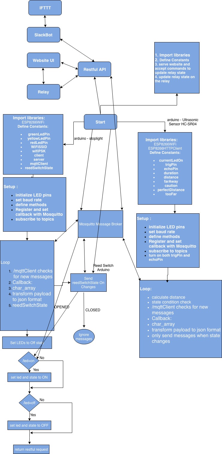
- System Flow: See Appendix 1.
Diagrams were facilitated by open source programs such as: Google drive plugin draw.io Diagrams.
- Program the code in the Arduino IDE
- Test/Debug to make sure the logic is sound. You can debug by first making sure the baud rate is set up in setup method. Then click on serial monitor icon
 .
. - Use commands such as Serial.println(<variableToBeEvaluated>) to print out debug messages, so you can make sure what you think the code is doing is actually happening.
- Test/Debug to make sure the logic is sound. You can debug by first making sure the baud rate is set up in setup method. Then click on serial monitor icon
Thought Questions
- How did you overcome the need for a full-featured interface, as well as the need for an accurate and easy to use interface?
The full feature interface was accomplished by utilizing two ESP8266. One to act as a rest server accepting requests via http listening for a specific endpoint and then forward the request to a message broker (MQTT) which then forward the message to the other ESP8266 sensors, send back the information the requestors (website and Slack bot). The second ESP8266 was utilized to host the website and send http requests to the first ESP8266 (rest server) then display the responses on the website UI. The easy to use interface leveraged the server by making http requests to it and responding back to the requestor in this case was a combination of IFTTT service called “If you enter an area, then make a web request” the web request was to the slack bot running at home which then checked if the garage door was closed, if so then send a pulse request to the Relay sensor, otherwise if the garage door was already opened just ignore the request (there is nothing to do since the garage door was already opened).
- What was the biggest challenge you overcame in this lab?
Wrapping my mind how I can make my private ISP network available to public internet. Slack bots can operate locally at my home, it creates a websocket with slack servers and are able to interact via through the websockets and webhooks thus allowing me to send commands to my local private internet at home.
- Please estimate the total time you spent on this lab and report.
- 1 hour building and refactoring the circuit and cluster of devices to work well.
- 8 hours coding the server and fixing bugs
- 2 hours working on the lab report using tools such as Google draw.io Diagrams and fritzing.
- 1 hours publishing a website with lab 5 instructions.
Certification of Work
I certify that the solution presented in this lab represents my own work. In the case where I have borrowed code or ideas from another person, I have provided a link to the author’s work in the references, and included a citation in the comments of my code.
— Lehi Alcantara
Appendix
Appendix 1: System Flowchart
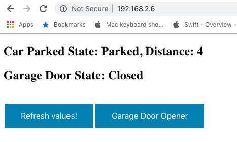
Appendix 2: User Interface Start
Appendix 3: User Interface Start After Fetching Data
Appendix 6: Arduino Code
(Available at https://github.com/ylehilds/iot-user-interface)


Comments
Post a Comment